GSM Module Troubleshooting
SIM800L power supply problem: complete Arduino and ESP32 fix guide
SIM800L modules often look defective when the real problem is power. If your module resets, blinks fast forever, ignores AT commands, fails to register on network, or crashes your ESP32/Arduino project, start with voltage, current, capacitor placement, grounding, and UART wiring.
Direct answer
Most SIM800L failures are power failures. Use a stable supply around 3.7V to 4.2V for common bare SIM800L boards, provide enough burst current, place a large capacitor near VCC/GND, share ground with the ESP32 or Arduino, then verify UART wiring and AT command responses.
Fast Diagnosis
90-second SIM800L power checklist
- Do not power a bare SIM800L module from ESP32 3.3V or Arduino 5V pins.
- Use a stable supply around 3.7V to 4.2V unless your exact breakout board specifies otherwise.
- Use a supply that can handle GSM current bursts, not just the idle current.
- Place a large electrolytic capacitor close to SIM800L VCC and GND.
- Connect MCU ground and SIM800L ground.
- Test with basic AT commands before adding sensors, cloud code, SMS logic, or GPRS code.
Symptoms and likely causes
| Symptom | Most likely cause | First fix to try |
|---|---|---|
| SIM800L keeps resetting | Voltage dips during GSM transmit bursts | Use a stronger 3.7V-4.2V supply and add a capacitor near the module |
| LED blinks fast forever | No network registration, weak signal, bad SIM, antenna issue, or unstable power | Check supply voltage under load, antenna, SIM status, and 2G network availability |
| No response to AT commands | TX/RX swapped wrong, baud mismatch, missing ground, or module not booted | Cross TX/RX correctly, share ground, and test with a simple serial sketch |
| Works once, then hangs | Power instability, blocking code, or serial buffer issues | Test AT commands only, then add application logic in small steps |
| ESP32 resets when SIM800L transmits | Shared weak supply or GSM burst pulling down the ESP32 rail | Separate module supply and keep grounds common |
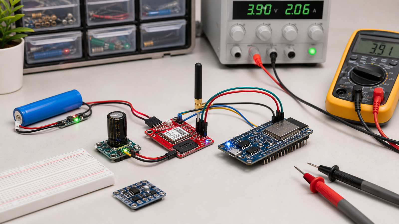
Power setup: the part most beginners get wrong
GSM modules do not behave like simple sensors. During network activity, SIM800L can demand short current bursts that are much higher than its idle current. A multimeter may show a normal voltage when idle, but the voltage can collapse during transmit bursts.
Check your exact module. Bare SIM800L boards are not usually 5V-tolerant at VCC.
Use a supply that can handle peak demand, not just average current.
Long wires reduce the benefit. Keep power wiring short and thick enough.

Some SIM800L breakout boards include regulators and may advertise a wider input range. Others expose the module supply directly. Do not assume all red SIM800L boards are wired the same. Check the seller page, silkscreen, regulator components, and measured VCC path.
UART wiring with Arduino or ESP32
Power problems are most common, but UART wiring problems are close behind. For serial communication, the transmitter of one device connects to the receiver of the other.
Basic UART connections
- MCU TX to SIM800L RXD
- SIM800L TXD to MCU RX
- MCU GND to SIM800L GND
- SIM800L VCC to suitable external supply
Common mistakes
- TX connected to TX and RX connected to RX
- No shared ground between microcontroller and module
- Wrong baud rate in serial code
- Using pins already occupied by USB serial or boot functions
SIM800L LED blink states
The onboard LED is useful, but it is not a complete diagnostic tool. Use it as a clue, then confirm with voltage measurement and AT commands.

Minimal AT command test flow
Before using SMS, HTTP, MQTT, GPS, cloud dashboards, or sensors, prove that the module responds to basic commands. This keeps firmware bugs separate from power and network problems.
AT
ATE0
AT+CPIN?
AT+CSQ
AT+CREG?
AT+COPS?| Command | What it checks |
|---|---|
| AT | Basic serial communication with the module |
| AT+CPIN? | SIM card status and PIN lock |
| AT+CSQ | Signal quality |
| AT+CREG? | Network registration status |
If power is stable but network still fails
- Confirm that your area still has 2G GSM service for the SIM/network you are using.
- Use an external antenna and keep it away from noisy wiring.
- Test the SIM card in a phone and disable SIM PIN lock.
- Check prepaid balance, SMS/data plan, APN settings, and operator restrictions.
- Move the setup near a window or open area for signal testing.
If the final device must be reliable, design retry logic, signal-quality checks, watchdog recovery, power rail monitoring, and clear status LEDs instead of assuming the GSM network will always be available.
Arduino vs ESP32 with SIM800L
Arduino Uno projects often use SoftwareSerial for SIM800L. ESP32 projects should use a hardware UART when possible. The ESP32 has multiple UARTs, which makes GSM communication more reliable when configured carefully.
- Use a hardware serial port on ESP32 for stable communication.
- Avoid pins that interfere with boot or flash operations.
- Do not run GSM burst current through the ESP32 board regulator.
- Keep GSM power and antenna layout in mind if you later design a PCB.
FAQ
Can I power SIM800L from Arduino 5V?
Usually no for bare SIM800L modules. Many SIM800L boards need around 3.7V to 4.2V with enough burst current. Some breakout boards include regulators, so check the exact board before applying 5V.
Why does SIM800L keep resetting?
The most common reason is voltage drop during GSM transmit bursts. Weak supplies, thin wires, missing capacitors, bad grounding, and poor USB power setups can all cause resets.
Why is my SIM800L LED blinking fast?
Fast blinking usually means the module is searching for network or not yet registered, but unstable power can also cause repeated searching and resets.
Do I need a capacitor for SIM800L?
In most beginner builds, yes. A large electrolytic capacitor close to VCC and GND helps handle short current bursts. It is not a substitute for a weak power supply, but it often improves stability.
Still stuck after power and AT command checks?
Get the free Electronics Project Rescue Pack. It includes power, wiring, module, sensor, and breadboard-to-PCB checklists for ESP32 and Arduino projects.
Get the free rescue pack