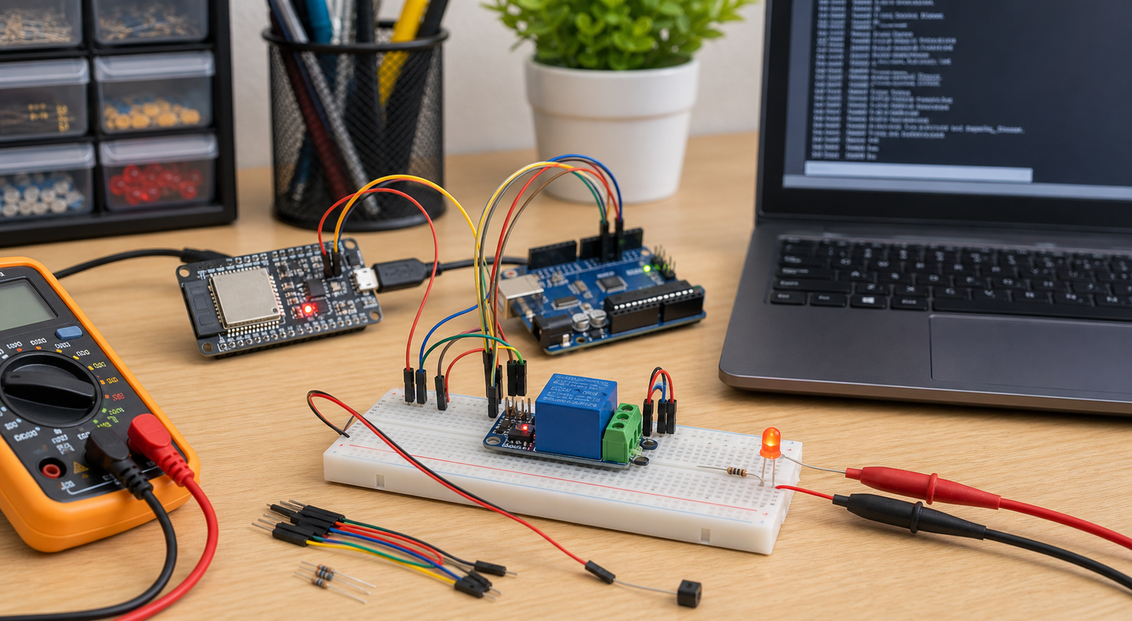
Relay Troubleshooting
Relay module always on: active low, NO/NC, and wiring fix guide
A relay module that looks “always on” is often working exactly as wired. The usual causes are active-low inputs, using NC instead of NO, floating GPIO pins, boot-time pin states, or confusing the relay LED with the actual load contact.
Direct answer
A relay module is usually always on because the module is active-low, the load is connected to NC instead of NO, the input pin is floating or pulled LOW at startup, the GPIO pin changes state during boot, or relay power/common ground wiring is wrong. Test with a low-voltage LED load and measure the IN pin before switching real loads.
Relay always-on symptoms and likely causes
| Symptom | Most likely cause | First fix to try |
|---|---|---|
| Relay turns on when GPIO is LOW | Active-low relay module | Invert the code logic: LOW = on, HIGH = off |
| Load is on even when relay LED is off | Load connected to NC terminal | Move load from NC to NO if it should be off by default |
| Relay clicks at boot | GPIO startup state or floating input | Use a safer GPIO and set output state early in setup |
| Relay never turns off with ESP32 | 3.3V logic compatibility, wiring, or module input circuit issue | Measure IN voltage and use a transistor/driver if needed |
| Relay LED changes but load does not | Wrong COM/NO/NC wiring or wrong load side being switched | Test contact continuity with a multimeter |
Relay always-on fix order

- Remove the real load and use a low-voltage LED or multimeter continuity test.
- Identify whether the relay module is active-low.
- Confirm the load is on NO if it should be off by default.
- Measure IN pin voltage when code says on and off.
- Check VCC, GND, JD-VCC jumper, and common ground requirements.
- Try a different GPIO if the relay turns on during boot.
- Test the relay module alone before adding sensors, WiFi, or heavy loads.
Active-low relay modules
Many popular relay modules are active-low. This means the relay energizes when the input pin is pulled LOW. The module may show labels like `LOW level trigger`, or the seller page may mention low-level trigger.
For an active-low relay, `digitalWrite(relayPin, LOW)` turns the relay on, and `digitalWrite(relayPin, HIGH)` turns it off.
COM, NO, and NC wiring
The relay contact side is separate from the input control side. If the load is connected to NC, it will be on when the relay is idle. That is correct behavior, not a software bug.
| Terminal | Meaning | Use when |
|---|---|---|
| COM | Common moving contact | Always part of the switched circuit |
| NO | Normally open | Load should be off when relay is idle |
| NC | Normally closed | Load should be on when relay is idle |
Do not test mains wiring on a breadboard. Use proper isolation, enclosure, fuse, wire gauge, and qualified inspection for AC loads.
GPIO startup states on Arduino and ESP32
During reset and boot, pins can float or change state before your code configures them. On ESP32, some pins also affect boot mode. If your relay clicks during startup, choose a safer GPIO and define the off state immediately.
- Avoid ESP32 boot strapping pins for relay control when possible.
- Use a pullup or pulldown that matches the relay module logic.
- Set the relay off state before long setup tasks such as WiFi connection.
- Test relay behavior during reset, upload, and power-on, not only after code is running.
Minimal active-low relay test code
Use this with a safe low-voltage test load. If your relay module is active-high, reverse the HIGH and LOW states.
const int relayPin = 5;

void setup() {
  pinMode(relayPin, OUTPUT);

  // Active-low relay: HIGH keeps relay off.
  digitalWrite(relayPin, HIGH);
}

void loop() {
  digitalWrite(relayPin, LOW);   // relay ON
  delay(2000);

  digitalWrite(relayPin, HIGH);  // relay OFF
  delay(2000);
}
JD-VCC and relay module power
Some relay boards include `JD-VCC`, `VCC`, and a jumper. These boards can separate relay coil power from logic power when wired correctly. If wired incorrectly, the relay may behave unpredictably or never release.
- Check the exact relay board documentation; modules differ.
- Do not power relay coils from a weak microcontroller pin.
- Use common ground when the relay input circuit requires it.
- If using ESP32 3.3V logic with a 5V relay board, verify input compatibility.
FAQ
Why is my relay module always on?
Common causes are active-low trigger logic, using NC instead of NO, GPIO startup states, floating input pin, wrong relay power wiring, missing common ground, or a damaged relay module.
What does active low relay mean?
An active-low relay module turns on when its input pin is LOW and turns off when the input pin is HIGH. This can make code appear inverted if you expect HIGH to mean on.
Should I use NO or NC on a relay?
Use NO if the load should be off when the relay is idle. Use NC only when the load should be on by default and turn off when the relay energizes.
Why does my relay turn on when Arduino or ESP32 starts?
The control pin may float or enter a startup state that triggers the relay before your setup code runs. Use a safer GPIO, pullup or pulldown, and set the off state early.
Relay still behaves backwards?
Get the free Electronics Project Rescue Pack. It includes relay, power, wiring, ESP32, Arduino, sensor, and breadboard-to-PCB checklists.
Get the free rescue pack