SIM800L Serial Troubleshooting
SIM800L no AT response: Arduino and ESP32 serial fix guide
When a SIM800L LED blinks but AT commands return nothing, the issue is usually UART wiring, baud rate, missing common ground, weak power, or using the wrong serial monitor settings.
Direct answer
If SIM800L gives no AT response, power it from a stable 3.7V-4.2V supply, connect grounds together, cross TX and RX correctly, try 9600 baud first, set the serial monitor line ending to both NL and CR, and test AT commands before adding network, SMS, or GPRS code.
Symptoms and likely causes
| Symptom | Likely cause | First fix |
|---|---|---|
| LED blinks but AT returns nothing | TX/RX wiring, baud rate, line ending, no common ground | Cross TX/RX and use both NL and CR |
| Random symbols in serial monitor | Wrong baud rate | Try 9600, 19200, 38400, 115200 |
| AT works once, then stops | Power dip or module reset | Use proper supply and capacitor near module |
| AT responds, network commands fail | Antenna, SIM, 2G network, APN, registration | Then use the SIM800L power and network guide |
SIM800L UART wiring
Serial wiring must be crossed. The microcontroller TX pin goes to SIM800L RX, and the SIM800L TX goes to the microcontroller RX. Ground must be common between the SIM800L power supply and the Arduino or ESP32.
Many SIM800L boards are not 5V-tolerant on RX. With Arduino Uno, use a simple level shifter or resistor divider from Arduino TX to SIM800L RX. ESP32 3.3V UART is usually safer.
Baud rate and serial monitor settings
Start with 9600 baud. If you see random characters, the wiring may be correct but the baud rate is wrong. Try common baud rates one by one. In Arduino IDE Serial Monitor, set line ending to both NL and CR, then send:
AT
ATI
AT+CSQ
AT+CREG?
`AT` should return `OK`. `ATI` prints module information. `AT+CSQ` checks signal quality. `AT+CREG?` checks network registration.
Power still matters for AT commands
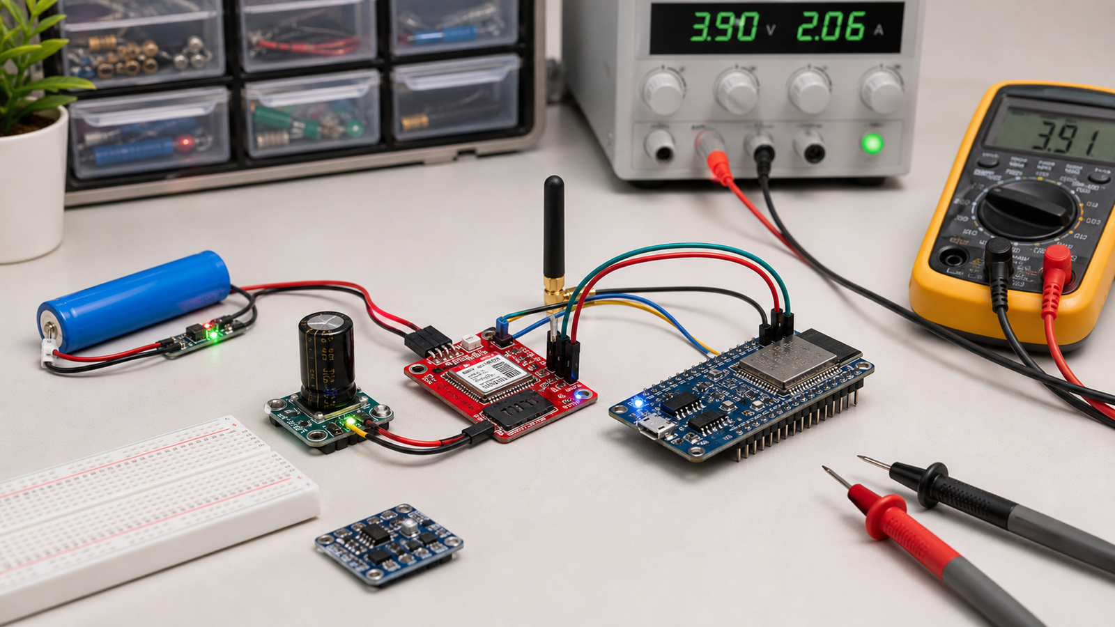
Even basic AT commands can fail if the module keeps resetting. SIM800L needs a supply around 3.7V-4.2V that can handle current bursts. Breadboard rails, long jumper wires, and weak regulators often cause resets that look like serial problems.
From Prototype to Product: Moving Beyond the Workbench
The SIM800L operates at a non-standard 2.8V serial voltage and requires brief, massive 2A current spikes during network transmission. For a commercial product, you must design a dedicated high-current power supply, logic level translation, and high-frequency RF layouts directly on your PCB.
The Productization Path for SIM800L Serial
FAQ
Why does SIM800L blink but not answer AT?
The module may be powered but the UART path is wrong. Check crossed TX/RX, common ground, baud rate, line endings, and power stability.
Can Arduino power SIM800L directly?
No, not reliably. Do not power SIM800L from the Arduino 5V or 3.3V pin. Use a separate supply designed for the module current demand.
Ready to productize your design?
Get the free Electronics Project Rescue Pack. It includes power, wiring, module, sensor, and breadboard-to-PCB checklists to help you move from a messy prototype to a release-ready custom PCB.
Download the rescue pack