Arduino Sensor Troubleshooting
Arduino sensor not working: wiring, code, and library fix guide
Most Arduino sensor problems are not caused by advanced code. They usually come from one wrong wire, missing ground, wrong voltage, wrong pin in code, or using a library example for a different sensor.
Direct answer
An Arduino sensor usually does not work because VCC/GND are wrong, the signal wire is on a different pin than the code expects, an analog sensor is wired to the wrong input, an I2C address or SDA/SCL wiring is wrong, the library does not match the sensor, or the breadboard/jumper connection is loose.
Arduino sensor symptoms and likely causes
| Symptom | Most likely cause | First fix to try |
|---|---|---|
| No reading at all | No power, missing ground, wrong signal pin, or wrong code | Check VCC, GND, signal pin, and print raw serial values |
| Always reads zero | Signal tied low, wrong analog pin, no sensor power, or bad module | Measure signal voltage and test a simple analog read |
| Always reads maximum | Signal pulled high, open circuit, wrong divider, or bad wiring | Move jumper wires and test the sensor alone |
| Shows NaN or failed reading | DHT-style timing, sensor type, DATA pin, or pullup problem | Use the DHT NaN guide and minimal DHT test code |
| I2C sensor not found | SDA/SCL swap, wrong address, missing pullups, wrong voltage | Run an I2C scanner before library examples |
Arduino sensor fix order

- Find the exact sensor model and pin labels.
- Connect VCC to the correct rail: 3.3V or 5V as required.
- Connect sensor GND to Arduino GND.
- Match the signal wire to the exact pin used in code.
- Run a minimal test sketch and print raw values.
- Only after raw values work, add displays, relays, motors, WiFi, or cloud code.
Know what kind of sensor you have
Different sensors need different debugging methods. Do not treat every sensor module as a simple digital input.
| Sensor type | Examples | Debug method |
|---|---|---|
| Analog | LDR divider, potentiometer, soil moisture analog output | Use `analogRead()` and print raw ADC values |
| Digital | PIR, tilt switch, obstacle sensor digital output | Use `digitalRead()` and check HIGH/LOW behavior |
| I2C | OLED, BMP/BME sensors, RTC modules | Run I2C scanner and use detected address |
| Timing protocol | DHT11, DHT22, ultrasonic sensors | Use correct library or pulse timing test |
| UART | GPS, fingerprint, some gas/PM sensors | Check TX/RX crossing, baud rate, and common ground |
Minimal analog sensor test code
For analog sensors, start with raw ADC values. If raw values do not move, calibration formulas will not help.
const int sensorPin = A0;

void setup() {
  Serial.begin(9600);
}

void loop() {
  int rawValue = analogRead(sensorPin);
  Serial.print("Raw sensor value: ");
  Serial.println(rawValue);
  delay(500);
}Move the sensor condition manually. Cover the LDR, turn the potentiometer, move an object, or change the measured input and watch whether raw values respond.
Breadboard and jumper wire problems
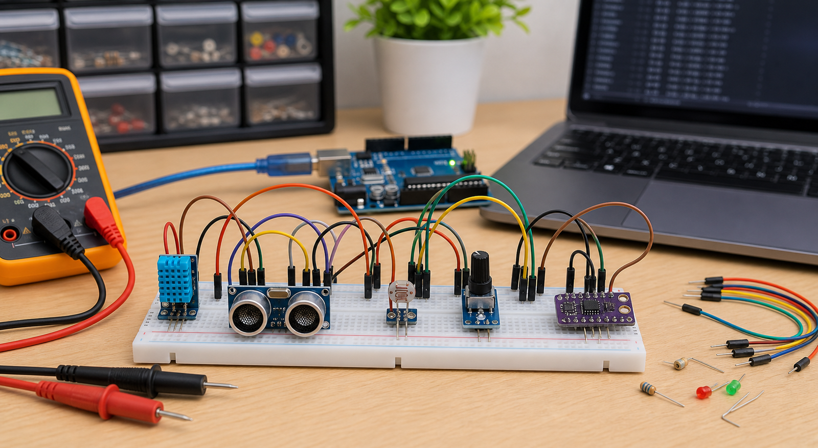
Beginner circuits often fail because the breadboard rails are split, jumper wires are loose, or the module is inserted into the wrong rows. A sensor can be wired "visually close" but electrically disconnected.
- Check whether the breadboard power rails are split in the middle.
- Use a multimeter to confirm 5V/3.3V reaches the sensor pins.
- Move jumper wires to fresh breadboard rows if readings are unstable.
- Do not trust wire color alone; follow the actual connection path.
- Test a second sensor if wiring and code are correct but output is impossible.
When the sensor works alone but fails in the project
If a sensor works in a minimal sketch but fails in the full build, the problem is usually timing, power, pin conflict, library conflict, or code structure.
- Check whether another module uses the same pin.
- Check whether a relay, motor, servo, or GSM module causes voltage dips.
- For I2C, scan with all modules connected and look for address conflicts.
- For DHT and timing-based sensors, avoid reading too fast.
- Print raw values before applying thresholds, calibration, or display formatting.
From Prototype to Product: Moving Beyond the Workbench
Getting clean, reliable sensor data on a breadboard is challenging due to contact resistance and electromagnetic noise. To productize a sensor design, you must design proper signal conditioning, decoupling, and analog layout directly onto your custom PCB.
The Productization Path for Arduino Sensors
FAQ
Why is my Arduino sensor not working?
The most common causes are wrong power voltage, missing ground, signal wire on the wrong pin, analog sensor connected to a digital-only pin, wrong library, wrong sensor type in code, loose breadboard wires, or a damaged sensor.
Why does my Arduino sensor always read zero?
A zero reading can come from no sensor power, missing ground, the signal pin tied to ground, wrong analog pin in code, wrong wiring, or using the wrong kind of sensor code.
Should I test Arduino sensors with full project code?
No. Test one sensor with a minimal sketch first. Once raw serial readings are stable, add displays, relays, WiFi, motors, or cloud code.
How do I know if the sensor is damaged?
If power, ground, signal wiring, code, library, and pin choice are correct, test another identical sensor or test the suspect sensor with another Arduino.
Ready to productize your design?
Get the free Electronics Project Rescue Pack. It includes power, wiring, module, sensor, and breadboard-to-PCB checklists to help you move from a messy prototype to a release-ready custom PCB.
Download the rescue pack